Welcome Anonymous !

Everything you need to modify your ride
 

Interior Modifications

BA/BF ICC (Radio) Mods and Hacking

Specific interior modification information for Ford BA and BF Series Falcons, Fairmonts, Fairlanes, LTD's and FPV models.

Postby Robertau » Tue Mar 01, 2016 2:30 pm

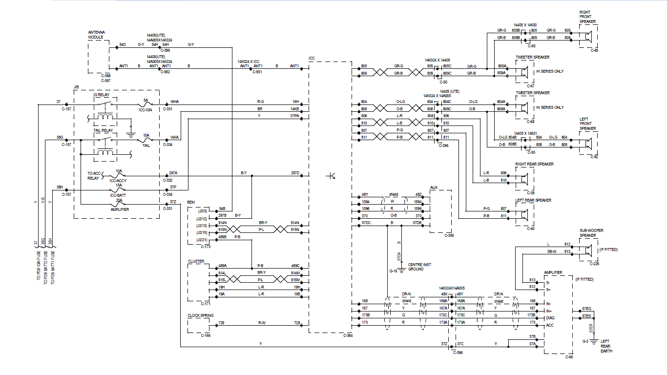
TazzI wrote:Right! So while I had the ignition barrel out.. I saw this little plug up in there.. not connected to anything.. any ideas??

Image
Image


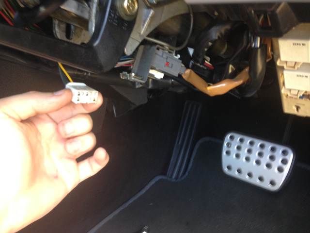
Thats the plug for the Adjustable Pedal Box, or more to the point the plug for the switch for adjustable pedals. :D


.
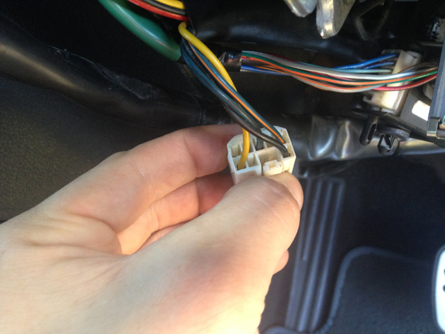
TazzI wrote:So I think those two plugs are the phone connector.. 4pin and 2pin connectors there.
Image

correct on the 4 pin and 2 pin plug.
the 4 pin plug is +12 Constant, ACC +12, Ground and phone mute.
the 2 pin plug is phone audio + and -

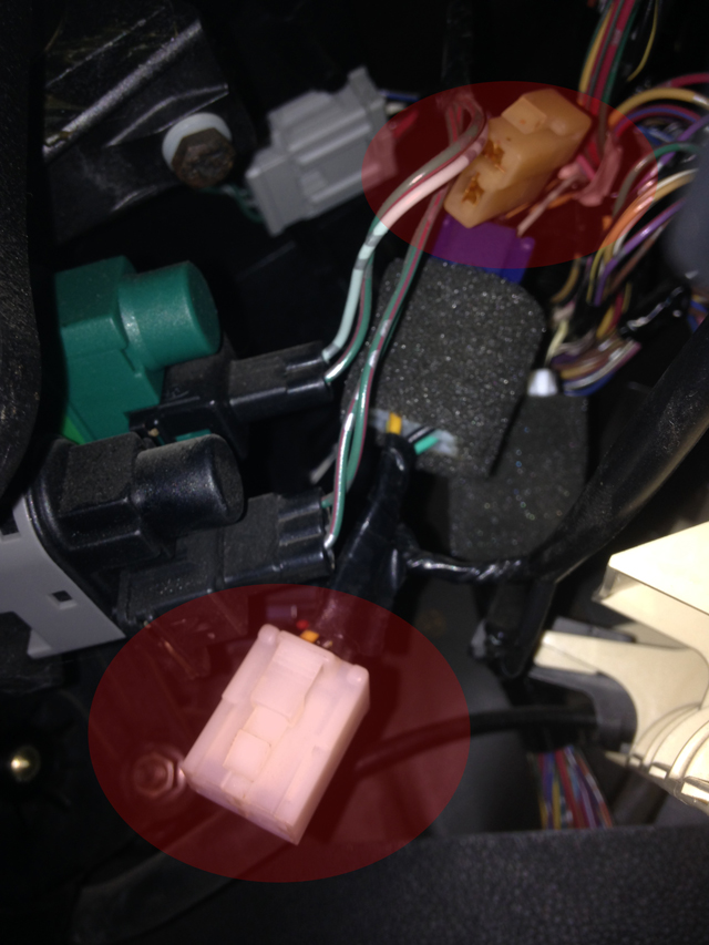
TazzI wrote:Annnnd... I didnt notice this plug before as its wrapped in foam.. but appears to be 6pin.. and its looping in on itself on one of the pins. I think tats the Aux plug..

Image


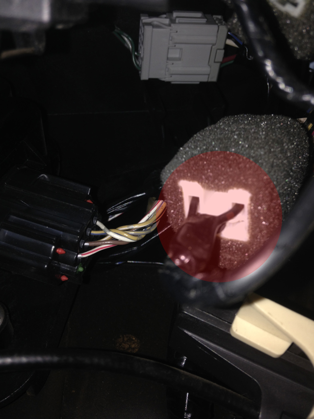
That does look like the AUX plug to me the top 2 in the pic are the ones that Loop back?

I'm 90% sure its the AUX plug on 2nd look

Rob
Robertau
Starting Ignition
 
Posts: 67
Joined: Mon Jan 19, 2015 2:31 pm
Has thanked: 0 time
Been thanked: 0 time

Postby TazzI » Tue Mar 01, 2016 3:12 pm

Cheers Rob!

I think it is, I was twisted up like a pretzel trying to get my head in there, so Ill unbolt the fuse box so I can get a better hold of it.

Will pull off that foam surround and unplug it, see if that disables the AUX on screen. :D
User avatar
TazzI
Moderator
 
Posts: 986
Images: 2
Joined: Thu Dec 22, 2011 8:02 pm
Has thanked: 16 times
Been thanked: 41 times

Postby TazzI » Wed Mar 02, 2016 10:38 am

Yep that was the aux plug.

Time to put together a dual aux style like you have Rob!
User avatar
TazzI
Moderator
 
Posts: 986
Images: 2
Joined: Thu Dec 22, 2011 8:02 pm
Has thanked: 16 times
Been thanked: 41 times

Postby GoFastBits » Wed Mar 02, 2016 10:20 pm

Weird that theres a bridge plug in there like that, does it actually have a harness on it running off somewhere (like the factory AUX?) that i can't see in the pics or is it literally just a plug with the aux enable loopback wire? :shock:
GoFastBits
Starting Ignition
 
Posts: 20
Joined: Wed Jan 06, 2016 11:08 pm
Has thanked: 0 time
Been thanked: 0 time

Postby TazzI » Thu Mar 03, 2016 11:56 am

GoFastBits wrote:Weird that theres a bridge plug in there like that, does it actually have a harness on it running off somewhere (like the factory AUX?) that i can't see in the pics or is it literally just a plug with the aux enable loopback wire? :shock:

I think it is a factory Aux on as it looks exactly like the ones Iv seen in other BA/BF's when Iv done work on them.

But yeah there is a loop back wire in the misc of that wrapped up wire.

Currently tracking down a plug, pins and parts to make up a dual aux version of it. :)
User avatar
TazzI
Moderator
 
Posts: 986
Images: 2
Joined: Thu Dec 22, 2011 8:02 pm
Has thanked: 16 times
Been thanked: 41 times

Postby Robertau » Thu Mar 03, 2016 12:41 pm

TazzI wrote:
GoFastBits wrote:Weird that theres a bridge plug in there like that, does it actually have a harness on it running off somewhere (like the factory AUX?) that i can't see in the pics or is it literally just a plug with the aux enable loopback wire? :shock:

I think it is a factory Aux on as it looks exactly like the ones Iv seen in other BA/BF's when Iv done work on them.

But yeah there is a loop back wire in the misc of that wrapped up wire.

Currently tracking down a plug, pins and parts to make up a dual aux version of it. :)


you should be able to get all 3 plugs from the back of a VT commodore? from memory out the trim and lights that fit in the boot lid (got mine of my brother) he was going to throw them out, even better is you'll get the matching sets if you take them out of both sides!

Rob
Robertau
Starting Ignition
 
Posts: 67
Joined: Mon Jan 19, 2015 2:31 pm
Has thanked: 0 time
Been thanked: 0 time

Postby TazzI » Thu Mar 03, 2016 4:21 pm

Robertau wrote:you should be able to get all 3 plugs from the back of a VT commodore? from memory out the trim and lights that fit in the boot lid (got mine of my brother) he was going to throw them out, even better is you'll get the matching sets if you take them out of both sides!

Rob


Thought about that, but as they are common automotive connectors, they should be readily available for purchase. Just a matter of tracking down the right plug!. Alot of sites only have datasheets.. and no actual pictures... so its gonna be a shot in the dark :lol:
User avatar
TazzI
Moderator
 
Posts: 986
Images: 2
Joined: Thu Dec 22, 2011 8:02 pm
Has thanked: 16 times
Been thanked: 41 times

Postby TazzI » Sat Mar 12, 2016 6:42 pm

I will never.. ever.. ever attempt getting a harness out of another Ford again. Gave up in the end and top the snips to the harness to start grabbing the connectors out for all the main modules.
Completely understand why wreckers have simply ignored my requests for the harness... its an absolute b**** of a job to get out.

But.. now its time to get some wiring diagrams flowing to fire up the ICC, cluster, HIM, BEM and ECU all up on bench.

Will start with the ICC first :D
User avatar
TazzI
Moderator
 
Posts: 986
Images: 2
Joined: Thu Dec 22, 2011 8:02 pm
Has thanked: 16 times
Been thanked: 41 times

Postby TazzI » Sat Mar 12, 2016 7:00 pm

(Excuse if the image is down.. seems my sever is having dramas...)
Sooooo. got the ICC wiring.. time to find the required wires...

Image


Sooo.. looks like the wires we need to fire it up and communicate are:

-Const Bat : Yellow
-Ignition : Red-Green
-Ground : Black
-ACC: Black-yellow
-CAN H : Brown-yellow
-CAN L : Pink-Blue

*Edit, confirmed the above by matching wires from diagnostics spec and power schematics

*Edit2: Updated to correct colour coding, thanks for pointing out Rob!
User avatar
TazzI
Moderator
 
Posts: 986
Images: 2
Joined: Thu Dec 22, 2011 8:02 pm
Has thanked: 16 times
Been thanked: 41 times

Postby Robertau » Sat Mar 12, 2016 7:22 pm

TazzI wrote:(Excuse if the image is down.. seems my sever is having dramas...)
Sooooo. got the ICC wiring.. time to find the required wires...

Image


Sooo.. looks like the wires we need to fire it up and communicate are:

-Const Bat : Yellow
-Ignition : Red-Green
-Ground : Blue
-ACC/lights: Blue-yellow
-CAN H : Brown-yellow
-CAN L : P-L

*Edit, confirmed the above by matching wires from diagnostics spec and power schematics


isnt it black for ground, black yellow for acc? thats how i have mine wired up and working.

blue in the SCH's is L im sure


Rob
Robertau
Starting Ignition
 
Posts: 67
Joined: Mon Jan 19, 2015 2:31 pm
Has thanked: 0 time
Been thanked: 0 time

PreviousNext

Return to Interior Modifications

  • View new posts
  • View unanswered posts
  • Who is online
  • In total there are 11 users online :: 0 registered, 0 hidden and 11 guests (based on users active over the past 5 minutes)
  • Most users ever online was 405 on Sat Mar 30, 2024 1:42 am
  • Users browsing this forum: No registered users and 11 guests