Hi Matti,
I have been reading allot of your posts around the place very interesting. I'm going to try and have a crack at this-
Transferring my eeprom data to the second hand one i just bought
Is this the right equipment?
USB KEEProg programmer - 24xx, 93xx, 25xx, 95xx eeproms and 3M SOIC 8 WAY Test Clips EEPROM / 93CXX / 25CXX / 24CXX
also found this reader http://www.chmaas.handshake.de/delphi/f ... /xvi32.htm to view and edit.
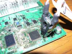
Also can save me a bit of time on how to identify the right eeprom chip to read and write to?(pic of board attached)
Cheers
Interior Modifications
VE Factory Body Control Module Information
38 posts
• Page 2 of 4 • 1, 2, 3, 4
![]() by ZerOne » Mon Aug 27, 2012 5:48 pm
by ZerOne » Mon Aug 27, 2012 5:48 pm
My Apologies for such a very very late post.
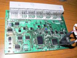
IC302 is the EEPROM IC, and it appears to be a 93xx66x16 EEPROM...
(It is labelled as a D93466
The Setting the above on my KeeProg programmer seems to give me what seems to be the best data...
And as promised (Months and Months ago), here is an EEPROM dump of an unknown Calais BCM.
(No idea what its from, all I know is that it is a Calais)
Part No : 25934763
Other Stuff : 20T874763LX80716363 (Dunno what this means, but its on the Denso Sticker)
TN232400-0195
You do not have the required permissions to view the files attached to this post.

![]() by ZerOne » Mon Aug 27, 2012 6:04 pm
by ZerOne » Mon Aug 27, 2012 6:04 pm
The VIN Number is located at EEPROM Locations
0x01E -> 0x02E (Full 17 Digit VIN Number)
and
0x0F6 -> 0x106 (Full 17 Digit VIN Number)
I can also confirm that I am able to read from, and write to the EEPROM using the KeeProg EEPROM programmer using the above settings,
without having to remove the EEPROM from the board. (However I needed to remove the resin from the chip to make a good electrical contact).
(Will try the GQ-4X EEPROM programmer next, to see if it can read and write whilst on the board)...
For anyone that wants to play at home, the EEPROM location is here.
![]() by ZerOne » Mon Aug 27, 2012 7:01 pm
by ZerOne » Mon Aug 27, 2012 7:01 pm
And here is the VE HSV BCM EEPROM
Part Number : 15921353
(20T)871353LX83375506
TN23400-240
Part Number : 15921353
(20T)871353LX83375506
TN23400-240
You do not have the required permissions to view the files attached to this post.
![]() by jezzab » Tue Aug 28, 2012 7:52 am
by jezzab » Tue Aug 28, 2012 7:52 am
Is that manual or auto that bin?
Daily Ute - 2009 Holden VE SSV Ute Single Turbo (IQ, E3 Cluster, EDI) - 586rwhp
Drag Ute - 2002 Holden VU SS Twin Turbo - 1010rwhp [SOLD]
All VE/VF Module reprogramming. Remote programming with flash box
http://www.facebook.com/jsbperformance
Drag Ute - 2002 Holden VU SS Twin Turbo - 1010rwhp [SOLD]
All VE/VF Module reprogramming. Remote programming with flash box
http://www.facebook.com/jsbperformance

![]() by ZerOne » Tue Aug 28, 2012 8:33 am
by ZerOne » Tue Aug 28, 2012 8:33 am
To be honest, I'm not too sure ?
It came from an eBay special, with a flip key, which I used to repair one of my other keys.
I'll try and look up the eBay listing, and get some more information.
(I don't even know if it came from a sedan or ute )
)
It came from an eBay special, with a flip key, which I used to repair one of my other keys.
I'll try and look up the eBay listing, and get some more information.
(I don't even know if it came from a sedan or ute
![]() by ZerOne » Tue Aug 28, 2012 12:16 pm
by ZerOne » Tue Aug 28, 2012 12:16 pm
Ok, did a bit of sleuthing...
It came from a water damaged (evoke coloured) VE Clubsport Sedan, with an M10 6 Speed Manual.
(Not sure if it is an E1 or E2 though)...
It came from a water damaged (evoke coloured) VE Clubsport Sedan, with an M10 6 Speed Manual.
(Not sure if it is an E1 or E2 though)...
![]() by harry2929 » Sun Oct 07, 2012 8:06 pm
by harry2929 » Sun Oct 07, 2012 8:06 pm
Hi could anyone please post a pic of how I can use the BCM to wire aftermarket fogs to my ve omega ( replace stock switch with sv6 switch ) a diagram for the entire setup would be much appreciated cheers  I have the lights and relay set up just need to know how I can mate it to the car to use the pull out sv6 switch
- harry2929
- Newbie Modder
- Posts: 1
- Joined: Sun Oct 07, 2012 7:51 pm
- Has thanked: 0 time
- Been thanked: 0 time
![]() by ZerOne » Tue Oct 23, 2012 12:11 pm
by ZerOne » Tue Oct 23, 2012 12:11 pm
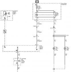
Here is some information on wiring the factory fog lamps switch, to the BCM,
and wiring the BCM output to the Fog lamp relay (For Omega and PPV export vehicles)
Fog Lamps Wiring Diagram
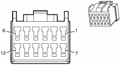
The Ligth Switch Wiring Connector Pin Outs
Note, I think Headlamp Dimming Switch Up and Down are meant to be Interior Lights Dimming Switch Up and Down. (Just copying straight from the manual, and I don't know if the Caprice auto level lamps can be adjusted via the light switch) ??
and wiring the BCM output to the Fog lamp relay (For Omega and PPV export vehicles)
Fog Lamps Wiring Diagram
The Ligth Switch Wiring Connector Pin Outs
- Code: Select all
Pin 1 - White - Headlamp Switch Headlamps On Signal
Pin 2 - Not Used
Pin 3 - Dark Green - Headlamp Switch Headlamps Off Signal
Pin 4 - Black - Ground (-) Voltage
Pin 5 - Brown/White - Park Lamp Switch On Signal
Pin 6 - Orange - Front Fog Lamp Switch Signal
Pin 7 - Grey/White - Headlamp Dimming Switch Down
Pin 8 - Yellow - Interior Lights Dimming Switch
Pin 9 - Not Used
Pin 10 - Pink/Blue - Ignition 1 Voltage
Pin 11 - Not Used
Pin 12 - Headlamp Dimming Switch Up
Note, I think Headlamp Dimming Switch Up and Down are meant to be Interior Lights Dimming Switch Up and Down. (Just copying straight from the manual, and I don't know if the Caprice auto level lamps can be adjusted via the light switch) ??
![]() by CesarKlein » Wed Sep 04, 2013 4:58 pm
by CesarKlein » Wed Sep 04, 2013 4:58 pm
ZerOne wrote:Body Control System Description and Operation
The body control system consists of the body control module (BCM), communications, and various input and outputs. Some inputs, outputs and messages require other modules to interact with the BCM. The BCM also has discrete input and output terminals to control the vehicle's body functions. The BCM is wired to the GMLAN High speed serial data buss and the GMLAN Low speed serial data buss and acts as a gateway between them. If the BCM does not communicate the vehicle will not start due to the inability of the engine control module (ECM) and theft deterrent module (TDM) to communicate without the BCM providing the gateway function.
Power Mode Master
This vehicles BCM functions as the power mode master (PMM). The ignition switch is a low current switch with multiple discrete ignition switch signals to the PMM for determination the power mode that will be sent over the serial data circuits to the other modules that need this information, and so the PMM will activate relays and other direct outputs of the PMM as needed. Refer to Power Mode Description and Operation for a complete description of power mode functions.
Serial Data Gateway
The BCM in this vehicle functions as a gateway or translator. The purpose of the gateway is to translate serial data messages between the GMLAN high speed buss and the GMLAN low speed buss for communication between the various modules. The gateway will interact with each network according to that network's transmission protocol.
One example of this necessary communication is the communication between the ECM which is high speed serial data and TDM which is low speed serial data. If these modules can not exchange information, the vehicle will not start.
Communication between the BCM and a scan tool can be on the high speed GMLAN network or low speed GMLAN network. If one network is lost, the BCM can still communicate with the scan tool. A lost communication DTC typically is set in modules other than the module with a communication failure.
Body Control Module
The various BCM input and output circuits are described in the corresponding functional areas indicated on the BCM electrical schematics. Some BCM functions with the subsystems may be as a gateway only or as an enable for the system. The BCM related systems/subsystems include, but are not limited to the following:
• Antilock Brake System (ABS)
• Cruise Control System
• Exterior led lights
• Horn System
• HVAC
• Instrument Cluster Indicator Control
• Interior Lighting
• Power Door Lock System
• Rear Window Defogger System
• Redundant Steering Wheel Controls
• Remote Function Actuation (RFA) control
• Retained Accessory Power (RAP)
• Shift Lock Control System - Automatic Transmission Shift Lock Control
• Starting System
• Supplemental Inflatable Restraint (SIR) System
• Vehicle Theft Deterrent and Immobilizer System
• Wiper/Washer System Functions
Thanks for sharing detailed information.. Just love the specifications but can you provide a short review abou the device..Waiting for reply thanks in advance:)
- CesarKlein
- Newbie Modder
- Posts: 1
- Joined: Wed Sep 04, 2013 3:44 am
- Has thanked: 0 time
- Been thanked: 0 time
38 posts
• Page 2 of 4 • 1, 2, 3, 4