The air temperature controls are divided into 4 areas:
• HVAC Control Components
• Heating and A/C Operation
• Engine Coolant
• A/C Cycle
HVAC Control Module
The HVAC control module is a GMLAN device that interfaces between the operator and the HVAC system to maintain air temperature and distribution settings. The HVAC module assembly is operated manually by a combination of electrical and mechanical components. The case is of a 3-piece, plastic construction. The left and right cases are assembled with a centre divider that houses the doors and are secured together with screws. The case sump is secured to the upper case assembly with screws. The blower resistor is integrated into the HVAC control module which is screwed to the HVAC blower motor fan assembly, which in turn is secured to the HVAC unit with a combination of pivot pins and screws.
A/C Pressure Sensor
The A/C refrigerant pressure sensor is a 3 wire piezoelectric pressure transducer. A 5 volt reference, low reference, and signal circuits enable the sensor to operate. The A/C pressure signal can be between 0-5 volts. When the A/C refrigerant pressure is low, the signal value is near 0 volts. When the A/C refrigerant pressure is high, the signal value is near 5 volts. The engine control module (ECM) converts the voltage signal to a pressure value.
It provides a 0-5 volt output and requires a 5 volt regulated power supply. In operation, the transducer senses applied pressure via the deflection of a 2 piece ceramic diaphragm with one half being a parallel plate capacitor. Changes in capacitance influenced by the refrigerant pressure under the ceramic diaphragm are converted to an analogue output by the transducers integral signal electronics. The pressure transducer's electronics are on a flexible circuit board contained in the upper section of the transducer. They provide linear calibration of the capacitance signal from the ceramic sensing diaphragm. Benefits of using the pressure transducer over a normal type pressure switch is that the transducer is constantly monitoring pressures and sending signals to the ECM. The normal type pressure switch only has an upper and lower cut out point. The ECM will disengage the A/C compressor at low or high refrigerant pressures and electronic diagnostic equipment can be used to extract system pressure information making it easier when diagnosing concerns. As well as acting as an input to the ECM for A/C operation, the ECM also uses the information provided by the pressure transducer to determine when to turn ON and OFF the 2nd Stage cooling fan operation.
Interior Modifications
VE Factory HVAC Information
20 posts
• Page 1 of 2 • 1, 2

![]() by ZerOne » Sat Feb 11, 2012 9:52 am
by ZerOne » Sat Feb 11, 2012 9:52 am
The purpose of the heating and A/C system is to provide heated and cooled air to the interior of the vehicle. The A/C system will also remove humidity from the interior and reduce windshield fogging. The vehicle operator can determine the compartment temperature by adjusting the air temperature switch. Regardless of the temperature setting, the following can affect the rate that the HVAC system can achieve the desired temperature:
• Recirculation actuator setting.
• Difference between inside and desired temperature.
• Difference between ambient and desired temperature.
• Blower motor speed setting.
• Mode setting.
The A/C system can be engaged by pressing the A/C switch. The A/C switch will illuminate when the A/C switch is pressed to the ON position. Pressing the A/C switch, the IRC (Radio) sends switch information via GMLAN to the HVAC. The HVAC unit then requests permission to engage the compressor from the ECM. Upon receiving permission from the ECM, the HVAC then engages the compressor.
• A/C Pressure is between 196 kPa (28 psi) and 3250 kPa (470 psi).
• Engine coolant temperature (ECT) is less than 119°C (250°F).
• Engine RPM is more than 400 RPM.
• The A/C request signal is set to engage.
Once engaged, the compressor will be disengaged for the following conditions:
• A/C Pressure is more than 3250 kPa (470 psi).
• A/C Pressure is less than 196 kPa (28 psi).
• ECT is more than 119°C (246°F).
• Throttle position is over 95 percent.
• Transmission shift
• ECM detects higher than predicted torque load.
• ECM detects insufficient idle quality.
• ECM detects a hard launch condition.
A/C Request Signal and A/C Control
The compressor is an externally controlled variable displacement (ECVD) compressor. The HVAC controls the compressor displacement with a pulse width modulated (PWM) signal. When the A/C switch is pressed, the HVAC requests permission to engage the compressor from the ECM. The ECM must grant this permission before the HVAC can engage the compressor. The BCM acts as a gateway to pass these messages on GMLAN between the HVAC (LS bus) and ECM (HS bus). If the conditions listed above are not met, the engine will not grant this permission and A/C will remain at approximately 4 cc (OFF). The A/C indication (LED/Icon) will remain ON. If A/C pressure is below 196 kPa the A/C will be reduced back to approximately 4 cc (turned OFF) and the A/C indication (LED/Icon) will turn OFF. This is a normal condition in very cold ambient temperatures. While the compressor is running the HVAC transmits a Normalised Load value (representing compressor torque) to the ECM. The ECM uses this value to manage engine torque requirements and maintain idle stability. The A/C will be reduced back to approximately 4 cc (turned OFF) if the HVAC fan is turned to zero (OFF).
Heater Core
The heater core is located within the HVAC case. The engine coolant flows through the heater core providing heat to warm the vehicle interior and to provide windscreen defogging. The heater core is of a tube and fin design and is constructed of aluminium. It is fitted with a detachable inlet and outlet pipe assembly. Each pipe is attached and sealed to the heater core. Sealing foam is bonded to the sides and around the top of the heater core to prevent air leakage from the HVAC case and to make sure that all air passes through the heater core in the full hot mode.
Radiator
The radiator is a heat exchanger. It consists of a core and 2 tanks. The aluminium core is a down flow tube and fin design. This is a series of tubes that extend vertically down from the inlet tank to the outlet tank. Fins are placed around the outside of the tubes to increase heat transfer from the coolant to the atmosphere. The inlet and outlet tanks are moulded with a high temperature, nylon reinforced plastic. A high temperature rubber gasket seals the tank flange edge. The tanks are clamped to the core with clinch tabs. The tabs are part of the aluminium header at each end of the core.
The radiator removes heat from the coolant passing through it. The fins on the core absorb heat from the coolant passing through the tubes. As air passes between the fins, it absorbs heat and cools the coolant.
During vehicle use, the coolant heats and expands. The coolant that is displaced by this expansion flows into the recovery reservoir bottle. As the coolant circulates, air is allowed to exit. This is an advantage to the cooling system. Coolant without bubbles absorbs heat much better than coolant with bubbles.
Evaporator
The evaporator is located inside the vehicle housed behind the instrument panel fascia in the HVAC case. It is constructed of aluminium and is of a plate and fin design. The evaporator core is the actual cooling unit of the A/C system. As the low pressure, low temperature refrigerant enters the evaporator, it begins to boil and evaporate. This evaporation process absorbs heat from the air being circulated through the evaporator core by the blower fan. Due to the evaporator being so cold, condensation forms on the surface. This condensation is moisture taken from the air (humidity). Also any dust particles in the air passing through the evaporator become lodged in the condensate water droplets, thus filtering the air from contaminants. The evaporator is constructed of aluminium and is fitted with a detachable inlet and outlet pipe assembly. It is attached and sealed to the evaporator by a single bolt and sealing washers
Condenser
The purpose of the condenser is the opposite of the evaporator. The condenser receives high pressure, high temperature refrigerant vapour from the compressor. It is exposed to a flow of ram air from the movement of the vehicle and as the high pressure high temperature vapour flows inside the condenser tubes, heat is given off to the cooler ambient air flowing past the condenser core. The vapour then condenses into a high pressure, high temperature liquid. Two cooling fans fitted to the rear of the radiator, are activated when required to assist in drawing cool air through the condenser.
Receiver Dehydrator
The receiver dehydrator acts as a particle filter, refrigerant storage container and most importantly, a moisture absorber. Moisture, temperature and R-134a causes hydrofluoric and hydrochloric acid. The silica gel beads (desiccant) located in the filter drier receiver absorb small quantities of moisture thus preventing acid establishment.
Thermal Expansion Valve (TXV)
The thermal expansion valve (TXV) controls refrigerant gas flow to the evaporator and make sure that complete evaporation takes place. It has 2 refrigerant passages. One is in the refrigerant line from the condenser to the evaporator and contains a ball and spring valve. The other passage is in the refrigerant line from the evaporator to the compressor and contains the temperature sensing element.
TXV Opening
As the non-cooled refrigerant from the evaporator core flows through the TXV outlet (suction), it makes contact with the underside of the thin metallic diaphragm and reacts on the refrigerant contained above that diaphragm. This refrigerant then expands, forcing the pin downwards and moving the ball off its seat, then compressing the spring and allowing more refrigerant to enter the evaporator.
TXV Closing
Operation is similar to opening but now the refrigerant from the evaporator is cold. The refrigerant contained above the diaphragm now contracts. The ball moves towards the seat aided by the compressed spring, reducing refrigerant flow. Low pressure liquid R-134a passing through the evaporator should be completely vaporized by the time it reaches the TXV outlet side. The TXV is installed in the engine bay to the right side of the instrument panel.
Compressor
The Denso compressor can match the air conditioning demand under all conditions without cycling. The basic compressor mechanism is a variable angle swash-plate with 6 axially oriented cylinders. The compressor has a pumping capacity of 160 cc.
The electronic control valve is installed in the compressor rear head. The swash-plate angle of the compressor and the resultant compressor displacement, are determined by the compressor crankcase to suction pressure differential which is governed by the control valve.
When the A/C capacity demand is low, the crankcase pressure behind the pistons is equal to the pressure in front of the pistons. This forces the swash plate to change its angle to towards vertical which reduces the stroke of the pistons and reduces the output of the compressor to approximately 4 cc. The evaporator cooling load is reduced, ambient temperature or blower fan speed is reduced and therefore, the suction pressure is reduced until it reaches the control point. To reach the control point, the electronic control valve assembly allows discharge pressure to bleed past the control valve ball valve seat and into the compressor crankcase. This crankcase pressure acts as an opposing force behind the compressor pistons to cause the swash plate to change its angle towards vertical and therefore, reduce piston stroke.
When the A/C capacity demand is high, the crankcase pressure behind the pistons is less than the pressure in front of the pistons. This forces the swash plate to change its angle away from vertical which increase the stroke of the pistons. The compressor will then have a corresponding increase in its displacement.
![]() by ZerOne » Sat Feb 11, 2012 9:53 am
by ZerOne » Sat Feb 11, 2012 9:53 am
Engine Coolant
The engine coolant is a solution made up of a 50-50 mixture of DEX-COOL and clean fresh water. The coolant solution carries excess heat away from the engine to the radiator, where the heat is dissipated to the atmosphere.
The engine coolant is a solution made up of a 50-50 mixture of DEX-COOL and clean fresh water. The coolant solution carries excess heat away from the engine to the radiator, where the heat is dissipated to the atmosphere.
![]() by ZerOne » Sat Feb 11, 2012 9:54 am
by ZerOne » Sat Feb 11, 2012 9:54 am
Cooling Fan Operation
The cooling fans operate in two stages; in both stages both fans run. In stage 1 the two fan motors are connected in series so both fans run at low speed. In stage 2 each fan motor is connected to battery voltage so both fans run at high speed. Cooling fan operation is controlled by the engine control module (ECM) based on inputs from the following:
• The A/C request signal
• The vehicle speed sensor (VSS)
• The A/C refrigerant pressure sensor
• The engine coolant temperature (ECT) sensor
Stage One - Both Fans Operate at Low Speed
When the conditions for Stage 1 operation are met the ECM provides a ground to the coil of engine cooling fan relay 1, causing it to operate (turn ON). The fan current path is then from the battery via the large radiator fan fuse, through the large fan motor, cooling fan relay 2, the small fan motor and cooling fan relay 1 to ground.
The conditions for Stage 1 operation are:
• There is an A/C request and:
• Vehicle speed is less than 30 km/h (19 mph)
• A/C refrigerant pressure is greater than 1517 kPa (220 psi).
• ECT is greater than 98°C (208°F).
• ECT is greater than 113°C (235°F) when the engine is switched off (in this case stage 1 will operate for approximately four minutes - this is referred to as low fan run-on).
• An ECT sensor fault is detected and a DTC is set.
Stage 1 operation will cease when:
• There is no A/C request and the ECT is less than 95°C (203°F).
• There is an A/C request and the vehicle speed is greater than 50 km/h (31 mph) and the A/C pressure is less than 1214 kPa (176 psi) and the ECT is less than 95°C (203°F).
• The vehicle speed is greater than 104 km/h (65 mph).
Stage Two - Both Fans Operate at High Speed
When the conditions for Stage 2 operation are met the ECM provides - in addition to that already provided for the coil of engine cooling fan relay 1 - a ground to the coils of engine cooling fan relays 2 and 3, causing them to operate (turn ON). For the large fan, the current path is then from the battery via the large radiator fan fuse, through the large fan motor and engine cooling fan relay 2 to ground. For the small fan, the current path is from the battery via the small radiator fan fuse, through engine cooling fan relay 3, through the small fan motor and engine cooling fan relay 1 to ground.
The conditions for Stage 2 operation are:
• The A/C refrigerant pressure is greater than 1758 kPa (255 psi).
• The ECT is greater than 108°C (226°F).
• An ECT sensor fault is detected and a DTC is set.
If stage 1 operation is off when the conditions for stage 2 operation are met, stage 2 operation will be initiated five seconds after initiation of Stage 1 operation.
Stage 2 operation will cease and revert to Stage 1 operation when:
• The ECT is less than 102°C (216°F).
• There is no A/C request.
• There is an A/C request and the A/C refrigerant pressure is less than 1517 kPa (220 psi).
• The vehicle speed is greater than 104 km/h (65 mph).
![]() by ZerOne » Sat Feb 11, 2012 9:57 am
by ZerOne » Sat Feb 11, 2012 9:57 am
A/C Cycle
Refrigerant is the key element in an air conditioning system. R-134a is a very low temperature gas that can transfer the undesirable heat and moisture from the passenger compartment to the outside air.
The A/C system used on this vehicle is a non-cycling system. Non-cycling A/C systems use a high pressure switch to protect the A/C system from a predetermined pressure. The high pressure switch will OPEN the electrical signal to the compressor if the refrigerant pressure becomes higher than required. After the high and the low sides of the A/C system pressure equalize, the high pressure switch will CLOSE. This completes the electrical circuit to the compressor. The A/C system is also mechanically protected with the use of a high pressure relief valve. If the high pressure switch were to fail or if the refrigerant system becomes restricted and refrigerant pressure continues to rise, the high pressure relief will pop open and release refrigerant from the system.
The A/C compressor is belt driven. The compressor builds pressure on the vapour refrigerant. Compressing the refrigerant also adds heat. The refrigerant is discharged from the compressor through the discharge hose, and forced through the condenser and then through the balance of the A/C system.
Compressed refrigerant enters the condenser at a high-temperature, high-pressure vapour state. As the refrigerant flows through the condenser, the heat is transferred to the ambient air passing through the condenser. Cooling causes the refrigerant to condense and change from a vapour to a liquid state.
The condenser is located in front of the radiator for maximum heat transfer. The condenser is made of aluminium tubing and aluminium cooling fins, which allows rapid heat transfer for the refrigerant. The semi-cooled liquid refrigerant exits the condenser and flows through the liquid line to the thermal expansion valve (TXV).
The TXV is located at the evaporator inlet. The TXV is the dividing point for the high and the low pressure sides of the A/C system. As the refrigerant passes through the TXV, the pressure on the refrigerant is lowered, causing the refrigerant to vaporise at the TXV. The TXV also measures the amount of liquid refrigerant that can flow into the evaporator.
Refrigerant exiting the TXV flows into the evaporator core in a low-pressure, liquid state. Ambient air is drawn through the HVAC module and passes through the evaporator core. Warm and moist air will cause the liquid refrigerant to boil inside the evaporator core. The boiling refrigerant absorbs heat from the ambient air and draws moisture onto the evaporator. The refrigerant exits the evaporator through the suction line and flows back to the compressor in a vapour state, completing the A/C cycle of heat removal. At the compressor, the refrigerant is compressed again and the cycle of heat removal is repeated.
The conditioned air is distributed through the HVAC module for passenger comfort. The heat and moisture removed from the passenger compartment condenses, and discharges from the HVAC module as water.
![]() by ZerOne » Sat Feb 11, 2012 10:06 am
by ZerOne » Sat Feb 11, 2012 10:06 am
VE Incar Ambiant Temperature Sensor Resistance Values
- Code: Select all
-15*C = 19.21K Ohm
-10*C = 14.18K Ohm
 -5*C = 10.77K Ohm
  0*C = 7.97K Ohm
  5*C = 6.39K Ohm
 10*C = 4.95K Ohm
 15*C = 3.91K Ohm
 20*C = 3.12K Ohm
 25*C = 2.52K Ohm
 30*C = 2.01K Ohm
 35*C = 1.60K Ohm
 40*C = 1.31K Ohm
 45*C = 1.09K Ohm
 50*C = 922 Ohm
 55*C = 764 Ohm
 60*C = 634 Ohm
 65*C = 529 Ohm
 70*C = 431 Ohm
![]() by ZerOne » Sat Feb 11, 2012 10:08 am
by ZerOne » Sat Feb 11, 2012 10:08 am
VE Outside Ambiant Temperature Sensor Resistance Values
- Code: Select all
-15*C = 36.29K Ohm
-10*C = 27.82K Ohm
 -5*C = 21.12K Ohm
  0*C = 16.33K Ohm
  5*C = 12.77K Ohm
 10*C = 9.88K Ohm
 15*C = 7.8K Ohm
 20*C = 6.22K Ohm
 25*C = 5K Ohm
 30*C = 4.01K Ohm
 35*C = 3.25K Ohm
 40*C = 2.66K Ohm
 45*C = 2.19K Ohm
 50*C = 1.80K Ohm
 55*C = 1.49K Ohm
 60*C = 1.24K Ohm
 65*C = 871 Ohm
![]() by ZerOne » Sat Feb 11, 2012 10:48 am
by ZerOne » Sat Feb 11, 2012 10:48 am
Automatic HVAC Description and Operation (RHD Except Long Wheelbase Sedan)
• Mode directions UP - Defrost, Bi-Level, Blend, Face, Floor
• A/C Compressor output - OFF/output increase
• Occupant climate control ON/OFF - Sleep mode, the air mix actuators are still operating in the back ground to try and maintain the selected set temperatures, which means at ON (wake up) the temperature output will be near the selected set temperatures.
• Fully automatic mode - auto text is illuminated when in fully automatic mode. auto text is off, the occupant climate control is in semi automatic mode.
• Temperature adjustment Driver Side - Set Temperature Range - Full cold to full hot, 17 to 30 in 1 (one) degree increments.
• Mode directions Down - Floor, Face, Blend, Bi-Level, Defrost.
• Blower speeds - Semi automatic mode Twenty (20) speeds. Fully automatic mode infinite speeds.
• Fresh / Recirculation - When in recirculation mode, will automatically go to fresh air after Thirty (30) minutes depending on ambient temperature.
• Temperature adjustment Passenger side - Set temperature range - Full cold to full hot, 17 to 30 in 1 (one) degree increments.
• Ambient temperature display - The ambient temperature is displayed on the infotainment facia when the button is pressed.
• Rear window defrost - Automatically turns off after 15 minutes the first time then every 5 minutes.
• Front windscreen defrost - In this mode the A/C is automatically ON, Recirculation is not allowed.
General Description
The VE occupant climate control HVAC will be provided in Two (2) Variants: Dual Zone (DZ) - Temperature adjustment is independent for both Passenger and Drivers side.
A module called the HVAC control module (HCM) is attached to the HVAC on the Passenger side is the micro processor used to monitor inputs, process data, calculate changes to operating functions and control HVAC outputs.
The Inputs are:
• Can Bus information - Priority key user, Engine RPM, Vehicle road speed, Coolant temperature, A/C system pressure via the pressure transducer.
• In-car temperature sensor.
• Ambient temperature sensor.
• Evaporative temperature sensor.
• Electric mode actuators (DC motors) voltage, position feed back via photo interrupters.
• Blower fan voltage.
• Ignition voltage.
• Sun load sensor.
• Variable stroke compressor electronic control valve displacement (ECVD) actual position.
The Outputs are:
• Air distribution mode - Face, Floor, Defrost, Blend, Bi-Level, Air intake and Rear Passenger.
• Vent temperatures by adjusting the air mixing doors, including the rear passenger.
• Blower fan speeds.
• Infotainment facia for display changes and Ambient temperature reading.
• Rear window defrost relay.
• Compressor displacement (output) via the ECVD. From OFF to Maximum output.
• Variable stroke compressor ECVD (electronic control valve) target position.
• Maximum blower fan speed relay.
Recommended Settings:
The vehicle owner should be encouraged to use the occupant climate control in fully Automatic mode and at a set temperature of between 22-24 degrees. Changing the set temperature to suit different conditions may cause the occupant climate control to behave differently from what the customer expects (eg. Setting to 17°C on a hot day may cause the customer to complain that the blower fan speed is too high).
Occupant Climate Control (OCC) When OFF is Selected:
The vehicle owner should be made aware that if the occupant climate control system is turned OFF, the following will occur:
• The air mixing (temperature) electric actuators will continue to operate (motor movement noise) in the background so as to make sure that when the occupant climate control system is re-activated it will be closer to the set temperature before the occupant climate control system was turned OFF.
• Default mode for the air inlet is fresh air, which will mean to the vehicle owner that even though the blower fan is not operating, when driving Ram air will forced into the HVAC. Depending on the set temperature before turning the occupant climate control OFF the vehicle owner may feel either too Hot or too Cold. If this is the case we suggest that they manually select Recirculation mode, this will prevent the Ram air from entering the HVAC
Automatic and Semi Automatic Mode - DZ and TZ:
The occupant climate control system should be set to automatic mode as in this mode the occupant climate control system will automatically control the vehicles interior temperature to the selected set temperature by the vehicles owner. The vehicle owner has the option of selecting semi automatic mode to "over rule" a function used in automatic mode. They might not like the blower fan speed selected in automatic mode, so they have the option of adjusting the Blower fan speed by operating that function on the infotainment facia, This will then take the occupant climate control system into semi automatic mode. This means that the occupant climate control system is still monitoring all the sensor readings and making automatic changes to mode and temperature, but - it can no longer use the blower motor as part of it’s calculations for altering the system, as the vehicle owner now has control of that function. The occupant climate control will try and compensate for having no blower fan speed control by altering another component to aid in meeting the required set interior temperature
Points to Remember on DZ Occupant Climate Control (OCC) Systems:
The occupant climate control system will alter mode positions, blower fan speeds and temperature in either automatic or semi automatic mode. These modes are face and floor. The passenger cannot have an individual blower speed from the driver as there is only one (1) blower motor in the HVAC.
Solar Load
The solar load sensor is located in the defrost panel of the crash pad. The sensor body houses two solar sensors, one for the passenger side and one for the driver side of the vehicle interior. These sensors are positioned at an approximate angle of 40 degrees so the side windows are also covered for solar load changes. A twilight sensor for automatic headlamp function is also contained in the solar sensor body.
Side Window Defrost Air Bleed from the HVAC - DZ :
As a design intention there is a constant bleed of air to the side windows in face mode. This air bleed is used to keep the side windows clear of any fogging that may be caused by the vehicle owner's breath exhaling, especially at low ambient temperatures. There is also an air bleed to defrost in floor mode
Evaporator Temperature Control
As the A/C system uses a Denso variable stroke and "clutchless" compressor that utilises an ECVD (electronic control valve) operated via the HVAC Control Module to increase or decrease the crankcase pressure in the compressor, which then alters the compressor output (displacement). The evaporator temperature sensor has no bearing on the cycling of the compressor as there is no direct or indirect electrical connection to the compressor from the vehicles wiring harness, as no clutch exists on the compressor. The compressor is operating constantly when the engine is operating, only the compressor output is adjusted. The evaporator temperature sensor is located in the lower section of the HVAC in the air intake stream after the evaporator and is used for sensing the incoming air temperature after the evaporator into the HVAC, to be used as part of the output calculation by the evaporator temperature sensor values are also required to operate the ECVD (electronic control valve) of the compressor to alter the stroke (displacement / output) for the A/C system.
Blower Fan Control:
• Automatic Mode - There are stepless and varying Blower fan speeds available. These are selected by the dependant on the input signals.
• Semi Automatic Mode - There are twenty (20) blower fan speeds available for selection by the vehicle owner.
The blower fan speeds are will vary according to:
• Vehicle road speed - When the vehicle is travelling down the highway, the ram air effect into the HVAC, in fresh air mode will increase the air force coming from the vents, so will decrease the blower fan speed to compensate for this ram air.
• In car temperature sensor.
• Ambient air temperature sensor.
• Solar load sensor - If the cabin temperature is at or near the set temperature, the blower fan will be at the minimum. An increase in sun load will cause the blower fan speed to increase.
Example: Ambient temperature 30 degree, high sun load, the blower fan will be on maximum to provide more cooling. If the vehicle enters a tunnel, all of a sudden the sun load has dramatically reduced, causing the vehicle owner to feel colder, The blower fan speed is reduced until the vehicle emerges from the tunnel.
• Drivers set temperature.
• Coolant temperature.
• Air distribution mode i.e.. Fresh or Recirculation mode.
• Ignition voltage.
Air Distribution Control
There are six distribution air modes that can be selected, either automatically or Semi Automatically. These are:
• Defrost.
• Blend (Floor and Defrost).
• Bi-Level (Floor and Face).
• Face.
• Floor.
• Centre console rear outlet.
When in Automatic mode and a set temperature above 25°C, only Floor and Defrost will be selected. If the set temperature is below 25°C, Face will be selected. If the vehicle interior temperature is at the desired temperature, the occupant climate control will select either Bi-Level (floor/face) or Face only, dependant on if the cabin temperature is required to warm up or cooled down. If cooling of the cabin is required, Floor mode may be selected for a short time (A/C purge), followed by Face mode. If heating of the cabin is required, Defrost mode will be selected until the engine coolant temperature is warm enough, this is called Defrost delay, then followed by Blend (floor/defrost). Then as the in car temperature increases, the mode should change to Bi-Level (floor/face). If heating is required and the coolant temperature is warm, Floor mode may be selected for a short time (Purge), followed by Bi-Level (floor/face) or Blend (floor/defrost), depending on conditions.
Air Inlet Control:
When Recirculation mode is selected either automatically or manually, the occupant climate control will return the air inlet to Fresh air mode after approximately 30 minutes, briefly and then will return to recirculation mode, this is to avoid a Carbon Dioxide build up in the cabin through exhaling by the vehicle occupants, which will cause drowsiness.
Automatic Mode:
The air inlet mode selected will vary according to:
• In car temperature.
• Ambient temperature.
• Solar load.
• Drivers set temperature.
• Start up conditions.
• Evaporator temperature.
• A/C High pressure.
• Engine coolant temperature.
If the vehicle cabin does not require cooling, fresh air will be selected. If extreme cooling of the vehicle cabin is required, such as when the ambient temperature is high and the vehicle has been standing in direct sunlight for an extended period, fresh may be selected for a short time (fresh delay), then recirculation mode until the vehicle cabin has cooled down. The Fresh air the engine bay cooling temperature becomes very high, Recirculation may be selected to increase cooling of the Vehicle Radiator.
Vent Air Temperature Control
The vent temperatures will vary between approximately 5 degrees C (Maximum cooling) and 70 degrees C (maximum heating). The temperature coming from the vent positions may / will be higher or lower than what is selected by the vehicle owner as a set temperature.
Semi Automatic Mode
This mode is where the passenger can adjust their set temperature, independent of the driver side set temperature. To access this mode when the driver set temp is in "locked mode", meaning that when the driver alters the set temperature, it alters both sides. For "unlocking mode", the passenger simply adjusts their temperature and the set temperature then becomes independent from the driver side set temperature. If the occupant climate control was in automatic mode the AUTO button LED illuminated, it will then go to semi automatic mode AUTO button LED not illuminated.
Automatic Mode
When a set temperature of between 17degrees C and 30 degrees C is selected, the air temperature will be controlled automatically. The Vent temperature will vary according to:
• In car temperature.
• Ambient temperature.
• Solar load.
• Driver or Passenger side set temperature.
When the vehicle cabin is at the desired temperature, the average vent air temperature should be the same as the set temperature. If the vehicle cabin requires cooling, the occupant climate control will try to control the vent temperature to less than the set temperature. If the vehicle cabin requires heating, the occupant climate control will try to control the vent temperature to be more than the set temperature. The more cooling required, the higher the vent temperature. Generally, the Blower fan speed will be low (less than 50%) before the occupant climate control starts to control the temperature. (e.g. When extreme cooling is required, the blower fan will start at maximum and the air mix will start at minimum. As the vehicle cabin temperature cools downs, the blower speed will decrease gradually.
• Increasing the set temperature will increase the vent temperature (providing air mix is not at maximum).
• Decreasing the set temperature will decrease the vent temperature (providing air mix is not at minimum).
• As the In car temperature increases, the vent temperature will decrease.
• As the Solar load decreases, the vent temperature will increase.
• As the Solar load increases, the vent temperature will decrease.
• As the Ambient temperature increases, the vent temperature will decrease.
• As the Ambient temperature decreases, the vent temperature will increase.
Occupant Climate Control (OCC) Cold Start Routines.
There are Four cold start routines incorporated into the occupant climate control system logic to cater for various conditions on first "key on" in the morning, typically at low ambient temperatures.
Each routine has its own respective set of criteria to satisfy before the routine is executed:
• Recirculation Delay: Automatically defaults to recirculation mode to prevent further ingress of cold air into the vehicle cabin.
• Defrost Delay: To reduce cold air at the floor during warm-up and prevents the driver breath from "fogging up" the front windscreen.
• HVAC Purge: Allows engine coolant to heat up the heater core and avoid humidity to face and windscreen when the blower fan is activated.
• A/C Purge: To avoid hot air blowing on face when the blower fan is activated.
• Fresh Delay: Uses cooler outside air to purge hot air from the vehicle.
![]() by ZerOne » Sat Feb 11, 2012 10:53 am
by ZerOne » Sat Feb 11, 2012 10:53 am
HVAC Unit Construction, Components and Associated Sensors
General Description
There is one type of Occupant Climate Control (OCC) HVAC module assemblies fitted across the VE Series Vehicle range:
Dual zone system-HVAC (OCC)
In-Car Temperature Sensor
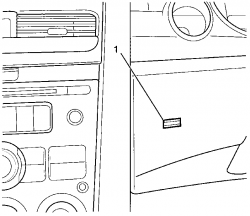
The in-car temperature sensor is an negative temperature coefficient (NTC) thermistor used to monitor the vehicles's interior temperature. Resistance signals are constantly monitored by the OCC module and are used for subsequent control of the OCC system.
It is essential that the venturi and aspirator tube assembly by properly connected to the in-car temperature sensor if the sensor is to provide correct information to the OCC module.
The in-car temperature sensor is located on the left-hand side of the steering column behind the sensor inlet air holes (1) on the instrument cluster trim assembly.
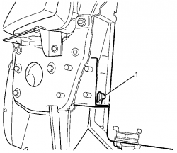
Evaporator Temperature Sensor
The evaporative temperature sensor is a negative temperature coefficient (NTC) thermistor used to monitor the temperature of the air into the HVAC module assembly after it has passed through the evaporator core. Resistance values are constantly monitored by the OCC module and are used for subsequent control of the OCC system.
The evaporative temperature sensor (1) is located on the HVAC case by a plastic retaining clip in the down stream air flow of the evaporator.
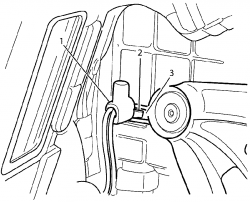
Ambient Temperature Sensor
The ambient temperature sensor (1) is installed on a bracket (2) that is located at the front of the A/C condenser (3), on the lower right-hand side.
It is a negative temperature coefficient NTC thermistor used to monitor the ambient (outside) temperature. This sensor is slow reacting, due to the dense plastic housing surrounding it. The OCC takes into account road speed before updating the temperature display to avoid false readings in heavy traffic or extended idle conditions.
Resistance signals are sent directly from the ambient temperature sensor to the OCC module for interpretation.
Sun Load Sensor
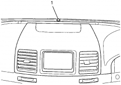
The sun load sensor (1) is located in the centre of the defrost panel to monitor the sun's heating load upon the vehicle.
It is a photochemical type sensor, where a small electrical current will be generated, which depending on the sun load (strength) over it. When the sun's intensity is high, the OCC module will select a higher blower fan speed and increased vehicle cooling automatically. Likewise, when the sun load is low, such as going into an underground car park, the OCC module will automatically reduce the fan speeds and increase heating slightly.
Signals are sent from the sun load senor directly to the BCM, then to the OCC module via the serial data line input.
General Description
There is one type of Occupant Climate Control (OCC) HVAC module assemblies fitted across the VE Series Vehicle range:
Dual zone system-HVAC (OCC)
In-Car Temperature Sensor
The in-car temperature sensor is an negative temperature coefficient (NTC) thermistor used to monitor the vehicles's interior temperature. Resistance signals are constantly monitored by the OCC module and are used for subsequent control of the OCC system.
It is essential that the venturi and aspirator tube assembly by properly connected to the in-car temperature sensor if the sensor is to provide correct information to the OCC module.
The in-car temperature sensor is located on the left-hand side of the steering column behind the sensor inlet air holes (1) on the instrument cluster trim assembly.
Evaporator Temperature Sensor
The evaporative temperature sensor is a negative temperature coefficient (NTC) thermistor used to monitor the temperature of the air into the HVAC module assembly after it has passed through the evaporator core. Resistance values are constantly monitored by the OCC module and are used for subsequent control of the OCC system.
The evaporative temperature sensor (1) is located on the HVAC case by a plastic retaining clip in the down stream air flow of the evaporator.
Ambient Temperature Sensor
The ambient temperature sensor (1) is installed on a bracket (2) that is located at the front of the A/C condenser (3), on the lower right-hand side.
It is a negative temperature coefficient NTC thermistor used to monitor the ambient (outside) temperature. This sensor is slow reacting, due to the dense plastic housing surrounding it. The OCC takes into account road speed before updating the temperature display to avoid false readings in heavy traffic or extended idle conditions.
Resistance signals are sent directly from the ambient temperature sensor to the OCC module for interpretation.
Sun Load Sensor
The sun load sensor (1) is located in the centre of the defrost panel to monitor the sun's heating load upon the vehicle.
It is a photochemical type sensor, where a small electrical current will be generated, which depending on the sun load (strength) over it. When the sun's intensity is high, the OCC module will select a higher blower fan speed and increased vehicle cooling automatically. Likewise, when the sun load is low, such as going into an underground car park, the OCC module will automatically reduce the fan speeds and increase heating slightly.
Signals are sent from the sun load senor directly to the BCM, then to the OCC module via the serial data line input.
20 posts
• Page 1 of 2 • 1, 2