3.6L Alloytec Dual Fuel LPG Engine - 4 Speed Automatic - 3.27 Non LSD Differential
3.0L SIDI Direct Injection Engine - 6 Speed Automatic - 3.27 Non LSD Differential
3.6L SIDI Direct Injection Engine - 6 Speed Automatic - 3.27 (Optional LSD on SV6 Models)
3.6L SIDI Direct Injection Engine - 6 Speed Manual - 3.27 LSD Differential
6.0L V8 L98/L76 Engine - 6 Speed Automatic - 2.92 Differential (LSD Standard on SS, SSV Models, optional on Calais, Calais V)
6.0L V8 L98/L76 Engine - 6 Speed Manual - 3.45 LSD Differential
HSV Automatic Models - 2.92 LSD Differential
HSV Manual Models - 3.45 LSD Differential
Differentail Fluid
Important: Both LSD and Non-LSD Differentials use the same fluid.
Differential Lubricant-Castrol SAF Carbon Mod. GM P/N 92184900
General Differential Information
VE Commodore Differential Specifications
7 posts
• Page 1 of 1

![]() by ZerOne » Fri Oct 28, 2011 8:23 pm
by ZerOne » Fri Oct 28, 2011 8:23 pm
Rear Drive Axle Description and Operation
The differential assembly is a cast aluminium two-piece housing design. The differential is mounted to the rear suspension assembly by three rubber mounts, one either side of the pinion flange at the front and the third at the rear of the housing. The differential housing retaining bolts are located around the outside of the housing with the four larger bolts are also bearing retaining bolts. The internal components incorporate a hypoid gear set, ring gear and pinion, carrier assembly and pinion housing assembly. Pinion bearing pre-load is created through a collapsible spacer. Torque is transferred from the propeller shaft to the differential via the pinion flange which is splined to the hypoid pinion. The torque is then transferred from the pinion through the ring gear, differential case, differential pinions, side gears, and then via splines to the wheel drive shafts.
The limited slip differential performs the same functions as the conventional type differential. However, should the one wheel begin to spin, it transfers driving force to the wheel with traction. It does this with a 5 plate clutch set up in the differential.
The limited slip differential as well as the conventional type differential are not serviceable items. The differentials are replaced as an assembly.
![]() by ZerOne » Fri Oct 28, 2011 8:29 pm
by ZerOne » Fri Oct 28, 2011 8:29 pm
Diff Parts
(1) Prevailing Torque Pinion Flange Nut
(2) Pinion Flange
(3) Pinion Flange Oil Seal
(4) Pinion Tail Bearing
(5) Right Front Bushing
(6) Pinion Tail Bearing Cup
(7) Differential Housing
(8) Drain/Fill Plugs
(9) Pinion Head Bearing Cup
(10) Collapsible Spacer
(11) Pinion Head Bearing
(12) Pinion Shim
(13) Pinion Gear
(14) Right Axle Shaft Seal
(15) Circlip
(16) Right Shim
(17) Differential Bearing Cup
(18) Differential Bearing
(19) Differential Assembly
(20) Ring Gear
(21) Differential Housing Cover
(22) Differential Retaining Bolt M10 (6x)
(23) Differential Housing Bolt M14 x 135mm (2x)
(24) Differential Housing Bolt M14 x 100mm (2x)
(25) Rear Bushing
(26) Ring Gear Bolts M12 (10x)
(27) Differential Bearing
(28) Differential Bearing Cup
(29) Left Shim
(30) Axle Shaft Seal
(31) Left Front Bushing
![]() by ZerOne » Fri Oct 28, 2011 8:32 pm
by ZerOne » Fri Oct 28, 2011 8:32 pm
Differential Service
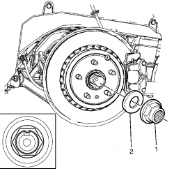
Important: The differential fill plug (1) and O-ring (3) come as an assembly, the O-ring (3) cannot be replaced separately.
Important: Clean the area around the differential fill plug (1) to prevent the entry of foreign particles into the differential (2).
•Remove the differential fill plug (1) from the differential (2).
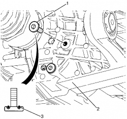
•Inspect the differential fill plug (1) and O-ring (3) for excessive wear and/or damage. Replace as necessary.
Important: The differential fluid level must be level with the bottom of the differential fill plug hole to no lower than 6 mm (0.25 in) below the opening.
Important: When adding differential fluid or making a complete differential fluid change, always use the correct differential fluid. Failure to use the correct differential fluid may cause gear damage and/or differential fluid leaks. For differential fluid specifications refer to Lubrication Specifications.
•Check the differential fluid level.
•Add new differential fluid if necessary.
Draining the Differential Oil
Remove the Differential Drain Plug, as shown in the following Image
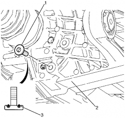
Important: The differential fill plug (1) and O-ring (3) come as an assembly, the O-ring (3) cannot be replaced separately.
Important: Clean the area around the differential fill plug (1) to prevent the entry of foreign particles into the differential (2).
•Remove the differential fill plug (1) from the differential (2).
•Inspect the differential fill plug (1) and O-ring (3) for excessive wear and/or damage. Replace as necessary.
Important: The differential fluid level must be level with the bottom of the differential fill plug hole to no lower than 6 mm (0.25 in) below the opening.
Important: When adding differential fluid or making a complete differential fluid change, always use the correct differential fluid. Failure to use the correct differential fluid may cause gear damage and/or differential fluid leaks. For differential fluid specifications refer to Lubrication Specifications.
•Check the differential fluid level.
•Add new differential fluid if necessary.
Draining the Differential Oil
Remove the Differential Drain Plug, as shown in the following Image
![]() by ZerOne » Fri Oct 28, 2011 8:47 pm
by ZerOne » Fri Oct 28, 2011 8:47 pm
Replacing the Differential
•Raise and support the vehicle. Refer to Lifting and Jacking the Vehicle.
•Remove the rear tyre and wheel assemblies. Refer to Tire and Wheel Removal and Installation.
•Drain differential oil. Refer to Differential Oil Replacement.
•Remove the intermediate exhaust assembly. Refer to Exhaust Crossover Pipe Replacement.
•Remove the rear exhaust muffler assemblies. Refer to Exhaust Muffler Replacement - Left Side and Exhaust Muffler Replacement - Right Side .
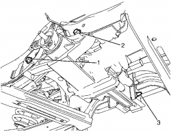
•Disconnect the left post-catalytic converter heated oxygen sensor (HO2S) electrical connector (1).
•Disconnect the right post-catalytic converter HO2S electrical connector (1).
Important: The intermediate exhaust assembly to left catalytic converter retaining nuts (3) are single use parts. They must be discarded after removal.
•Remove the intermediate exhaust assembly to left catalytic converter retaining nuts (3).
Discard the nuts.
•Disconnect the intermediate exhaust assembly (2) from the left catalytic converter (1).
Important: The intermediate exhaust assembly to right catalytic converter retaining nuts (3) are single use parts. They must be discarded after removal.
•Remove the intermediate exhaust assembly to right catalytic converter retaining nuts (3).
Discard the nuts.
•Disconnect the intermediate exhaust assembly (2) from the right catalytic converter (1).
•Remove the intermediate exhaust assembly to rear muffler retaining bolts (3).
•Detach the intermediate exhaust assembly (2) by removing the front insulator hangers (1) if fitted.
•Detach the intermediate exhaust assembly (2) by removing the centre insulator hanger bracket to differential retaining bolt (1).
•Carefully lower the intermediate exhaust assembly from the vehicle.
•Remove the left post-catalytic converter HO2S. Refer to Heated Oxygen Sensor Replacement - Bank 1 Sensor 2 or Heated Oxygen Sensor Replacement - Bank 1 Sensor 2 .
•Remove the right post-catalytic converter HO2S. Refer to Heated Oxygen Sensor Replacement - Bank 2 Sensor 2 or Heated Oxygen Sensor Replacement - Bank 2 Sensor 2 .
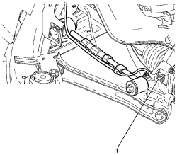
•Remove the propeller shaft and rubber coupling from differential flange. Refer to Propeller Shaft Replacement below.
•Remove the wheel drive shaft assemblies. Refer to Wheel Drive Shaft Replacement.
•Support the differential with a suitable jack
Important: Nuts with micro-encapsulated thread sealant are single use parts and must be discarded after removal.
•Remove the differential retaining bolts and nuts (1), (2) and (3) from the rear suspension.
Important: With a suitable jack support the differential.
•Remove the differential from the vehicle.
•Raise and support the vehicle. Refer to Lifting and Jacking the Vehicle.
•Remove the rear tyre and wheel assemblies. Refer to Tire and Wheel Removal and Installation.
•Drain differential oil. Refer to Differential Oil Replacement.
•Remove the intermediate exhaust assembly. Refer to Exhaust Crossover Pipe Replacement.
•Remove the rear exhaust muffler assemblies. Refer to Exhaust Muffler Replacement - Left Side and Exhaust Muffler Replacement - Right Side .
•Disconnect the left post-catalytic converter heated oxygen sensor (HO2S) electrical connector (1).
•Disconnect the right post-catalytic converter HO2S electrical connector (1).
Important: The intermediate exhaust assembly to left catalytic converter retaining nuts (3) are single use parts. They must be discarded after removal.
•Remove the intermediate exhaust assembly to left catalytic converter retaining nuts (3).
Discard the nuts.
•Disconnect the intermediate exhaust assembly (2) from the left catalytic converter (1).
Important: The intermediate exhaust assembly to right catalytic converter retaining nuts (3) are single use parts. They must be discarded after removal.
•Remove the intermediate exhaust assembly to right catalytic converter retaining nuts (3).
Discard the nuts.
•Disconnect the intermediate exhaust assembly (2) from the right catalytic converter (1).
•Remove the intermediate exhaust assembly to rear muffler retaining bolts (3).
•Detach the intermediate exhaust assembly (2) by removing the front insulator hangers (1) if fitted.
•Detach the intermediate exhaust assembly (2) by removing the centre insulator hanger bracket to differential retaining bolt (1).
•Carefully lower the intermediate exhaust assembly from the vehicle.
•Remove the left post-catalytic converter HO2S. Refer to Heated Oxygen Sensor Replacement - Bank 1 Sensor 2 or Heated Oxygen Sensor Replacement - Bank 1 Sensor 2 .
•Remove the right post-catalytic converter HO2S. Refer to Heated Oxygen Sensor Replacement - Bank 2 Sensor 2 or Heated Oxygen Sensor Replacement - Bank 2 Sensor 2 .
•Remove the propeller shaft and rubber coupling from differential flange. Refer to Propeller Shaft Replacement below.
•Remove the wheel drive shaft assemblies. Refer to Wheel Drive Shaft Replacement.
•Support the differential with a suitable jack
Important: Nuts with micro-encapsulated thread sealant are single use parts and must be discarded after removal.
•Remove the differential retaining bolts and nuts (1), (2) and (3) from the rear suspension.
Important: With a suitable jack support the differential.
•Remove the differential from the vehicle.
![]() by ZerOne » Wed Dec 28, 2011 9:55 am
by ZerOne » Wed Dec 28, 2011 9:55 am
Propeller Shaft Replacement (Except 4L60)
Removal Procedure
•Select park/1st gear position in the transmission and apply the park brake.
Warning: Refer to Safety Glasses Warning in the Preface section.
Danger: To avoid any vehicle damage, serious personal injury or death when major components are removed from the vehicle and the vehicle is supported by a hoist, support the vehicle with jack stands at the opposite end from which the components are being removed and strap the vehicle to the hoist.
•Raise and support the vehicle. Refer to Lifting and Jacking the Vehicle.
•Remove the intermediate exhaust assembly. Refer to Exhaust Crossover Pipe Replacement.
•Remove the propeller shaft heat shield. Refer to Exhaust Heat Shield Replacement - Center.
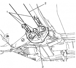
Note: Observe the orientation of the rubber couplings with reference to the differential flange and the transmission flange. This will minimise the potential of incorrect propeller shaft installation.
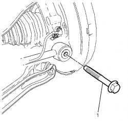
•Mark the rubber coupling (1) in relation to the differential flange (2).
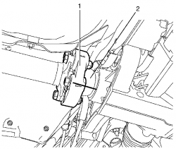
Note: With the aid of an assistant or suitable jack support the propeller shaft (2).
•Remove the rubber coupling to differential flange retaining bolts (1).
Note: Observe the orientation of the rubber couplings with reference to the differential flange and the transmission flange. This recommendation will minimise the potential of incorrect propeller shaft installation.
•Mark the rubber coupling (2) in relation to the transmission flange (1).
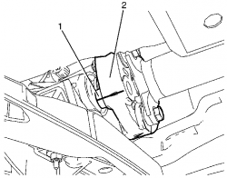
Note: With the aid of an assistant or suitable jack support the propeller shaft.
Note: Torque prevailing nuts with are single use parts and must be discarded after removal.
•Remove the rubber coupling to transmission flange retaining bolts (1) and torque prevailing nuts (2).
Discard the nuts.
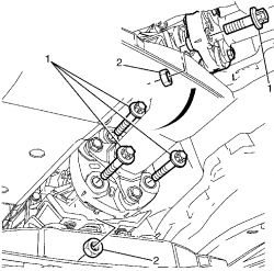
Note: With the aid of an assistant or suitable jack support the propeller shaft (2).
•Remove the centre bearing to body retaining bolts (1).
•Disconnect the propeller shaft (2) from the differential flange.
•Remove the propeller shaft (2) from the vehicle.
•Inspect the propeller shaft (2) assembly for excessive wear and/or damage. Inspect the following:
• Rubber coupling. For replacement refer to Rear Propeller Shaft Coupling Replacement.
• Centre bearing. For replacement refer to Propeller Shaft Center Support Bearing Replacement.
• Universal joint. For replacement refer to Universal Joint Replacement.
Removal Procedure
•Select park/1st gear position in the transmission and apply the park brake.
Warning: Refer to Safety Glasses Warning in the Preface section.
Danger: To avoid any vehicle damage, serious personal injury or death when major components are removed from the vehicle and the vehicle is supported by a hoist, support the vehicle with jack stands at the opposite end from which the components are being removed and strap the vehicle to the hoist.
•Raise and support the vehicle. Refer to Lifting and Jacking the Vehicle.
•Remove the intermediate exhaust assembly. Refer to Exhaust Crossover Pipe Replacement.
•Remove the propeller shaft heat shield. Refer to Exhaust Heat Shield Replacement - Center.
Note: Observe the orientation of the rubber couplings with reference to the differential flange and the transmission flange. This will minimise the potential of incorrect propeller shaft installation.
•Mark the rubber coupling (1) in relation to the differential flange (2).
Note: With the aid of an assistant or suitable jack support the propeller shaft (2).
•Remove the rubber coupling to differential flange retaining bolts (1).
Note: Observe the orientation of the rubber couplings with reference to the differential flange and the transmission flange. This recommendation will minimise the potential of incorrect propeller shaft installation.
•Mark the rubber coupling (2) in relation to the transmission flange (1).
Note: With the aid of an assistant or suitable jack support the propeller shaft.
Note: Torque prevailing nuts with are single use parts and must be discarded after removal.
•Remove the rubber coupling to transmission flange retaining bolts (1) and torque prevailing nuts (2).
Discard the nuts.
Note: With the aid of an assistant or suitable jack support the propeller shaft (2).
•Remove the centre bearing to body retaining bolts (1).
•Disconnect the propeller shaft (2) from the differential flange.
•Remove the propeller shaft (2) from the vehicle.
•Inspect the propeller shaft (2) assembly for excessive wear and/or damage. Inspect the following:
• Rubber coupling. For replacement refer to Rear Propeller Shaft Coupling Replacement.
• Centre bearing. For replacement refer to Propeller Shaft Center Support Bearing Replacement.
• Universal joint. For replacement refer to Universal Joint Replacement.
![]() by ZerOne » Wed Dec 28, 2011 10:13 am
by ZerOne » Wed Dec 28, 2011 10:13 am
Wheel Drive Shaft Replacement
•Raise and support the vehicle. Refer to Lifting and Jacking the Vehicle.
•Remove the rear tyre and wheel assemblies. Refer to Tire and Wheel Removal and Installation.
•Install the KM-468-C (1) to the wheel hub (2) with two inverted wheel nuts (3).
•Support the KM-468-C (1) outer end on a safety stand.
Important: Use a suitable tool to release the crimping on the wheel drive shaft retaining nut.
Important: The wheel drive shaft retaining nut (1) must be discarded after removal.
•Remove the wheel drive shaft retaining nut (1).
Discard the nut.
•Remove the wheel drive shaft washer (2).
Discard the washer.
•Remove the KM-468-C from the wheel hub.
•Disconnect the wheel speed sensor electrical connector (1).
•Detach the wheel speed sensor wiring harness mounting clip (2) from the knuckle (3).
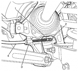
Important: Using a suitable tool, detach the rear park brake cable and clevis (1) from the park brake actuator (2) by pivoting the rear park brake cable and clevis (1) rearward.
•Detach the rear park brake cable and clevis (1) from the park brake actuator (2).
Important: Remove the outer cable (4) from the rear knuckle (3) by pulling the outer cable (4) forward.
•Remove the outer cable (4) from the rear knuckle (3).
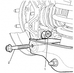
Important: Nuts with micro-encapsulated thread sealant must be discarded after removal.
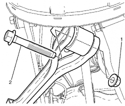
•Remove the lower control arm to knuckle retaining bolt (2) and nut (1).
Discard the nut.
•Remove the I-Link to knuckle retaining bolt (1) and washer (2).
•Remove the Y-Link to the knuckle retaining bolt (2) and nut (1).
Discard the nut
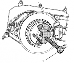
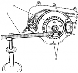
Important: Do not hammer the end of the wheel drive shaft to remove use J 42129 .
•Use J 42129 to remove the wheel drive shaft (1) from the wheel hub assembly (2).
•Place a suitable container under the differential in order to collect draining fluid.
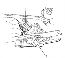
Important: Do not pull on the interconnecting shaft as it will pull apart the inboard joint.
Important: Do not damage the axle seal when disconnecting the wheel drive shaft (1) from the differential (2). Cuts or abrasions will damage the axle seal and result in lubricant leakage from this area.
Important: Use a suitable tool to pry the inner constant velocity joint out of the differential to release the snap ring.
Important: Support the wheel drive shaft when removing as the rear subframe may cut the inner constant velocity boot.
•Disconnect the wheel drive shaft (1) from the differential (2).
•Remove the wheel drive shaft (1) from the vehicle.
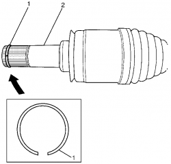
Important: The snap ring (1) is a single use part and must be discarded after removal.
•Remove the snap ring (1) from the inner constant velocity joint (2).
Discard the snap ring.
•Inspect the wheel drive shaft assembly for excessive wear and/or damage. Inspect the following:
• Wheel Drive Shaft.
• Inner Joint Boot. For replacement refer to Rear Wheel Drive Shaft Inner Joint Boot Replacement.
• Inner Constant Velocity Joint. For replacement refer to Wheel Drive Shaft Inner Joint and Boot Replacement.
• Outer Joint Boot. For replacement refer to Rear Wheel Drive Shaft Outer Joint Boot Replacement.
• Outer Constant Velocity Joint. For replacement refer to Wheel Drive Shaft Outer Joint and Boot Replacement.
•Raise and support the vehicle. Refer to Lifting and Jacking the Vehicle.
•Remove the rear tyre and wheel assemblies. Refer to Tire and Wheel Removal and Installation.
•Install the KM-468-C (1) to the wheel hub (2) with two inverted wheel nuts (3).
•Support the KM-468-C (1) outer end on a safety stand.
Important: Use a suitable tool to release the crimping on the wheel drive shaft retaining nut.
Important: The wheel drive shaft retaining nut (1) must be discarded after removal.
•Remove the wheel drive shaft retaining nut (1).
Discard the nut.
•Remove the wheel drive shaft washer (2).
Discard the washer.
•Remove the KM-468-C from the wheel hub.
•Disconnect the wheel speed sensor electrical connector (1).
•Detach the wheel speed sensor wiring harness mounting clip (2) from the knuckle (3).
Important: Using a suitable tool, detach the rear park brake cable and clevis (1) from the park brake actuator (2) by pivoting the rear park brake cable and clevis (1) rearward.
•Detach the rear park brake cable and clevis (1) from the park brake actuator (2).
Important: Remove the outer cable (4) from the rear knuckle (3) by pulling the outer cable (4) forward.
•Remove the outer cable (4) from the rear knuckle (3).
Important: Nuts with micro-encapsulated thread sealant must be discarded after removal.
•Remove the lower control arm to knuckle retaining bolt (2) and nut (1).
Discard the nut.
•Remove the I-Link to knuckle retaining bolt (1) and washer (2).
•Remove the Y-Link to the knuckle retaining bolt (2) and nut (1).
Discard the nut
Important: Do not hammer the end of the wheel drive shaft to remove use J 42129 .
•Use J 42129 to remove the wheel drive shaft (1) from the wheel hub assembly (2).
•Place a suitable container under the differential in order to collect draining fluid.
Important: Do not pull on the interconnecting shaft as it will pull apart the inboard joint.
Important: Do not damage the axle seal when disconnecting the wheel drive shaft (1) from the differential (2). Cuts or abrasions will damage the axle seal and result in lubricant leakage from this area.
Important: Use a suitable tool to pry the inner constant velocity joint out of the differential to release the snap ring.
Important: Support the wheel drive shaft when removing as the rear subframe may cut the inner constant velocity boot.
•Disconnect the wheel drive shaft (1) from the differential (2).
•Remove the wheel drive shaft (1) from the vehicle.
Important: The snap ring (1) is a single use part and must be discarded after removal.
•Remove the snap ring (1) from the inner constant velocity joint (2).
Discard the snap ring.
•Inspect the wheel drive shaft assembly for excessive wear and/or damage. Inspect the following:
• Wheel Drive Shaft.
• Inner Joint Boot. For replacement refer to Rear Wheel Drive Shaft Inner Joint Boot Replacement.
• Inner Constant Velocity Joint. For replacement refer to Wheel Drive Shaft Inner Joint and Boot Replacement.
• Outer Joint Boot. For replacement refer to Rear Wheel Drive Shaft Outer Joint Boot Replacement.
• Outer Constant Velocity Joint. For replacement refer to Wheel Drive Shaft Outer Joint and Boot Replacement.
7 posts
• Page 1 of 1